
[ad_1]
– Commercial –

Contemplate this digital stopwatch with twin timers in case you are searching for a twin stopwatch that permits you to measure two distinct time intervals. It options two unbiased shows, which will be chosen utilizing the mode change change. Here’s a normal information on utilizing this twin stopwatch:
1. Begin/cease performance: Most twin stopwatches have separate buttons to begin and cease every timer independently. On this stopwatch, you additionally press the ‘Begin’ button for every timer to provoke time measurement and launch the identical change to cease the stopwatch. (Right here we use push-to-on switches S1 and S2.)
2. Mode change performance: Some stopwatches have a mode change perform that enables them to alter time in both seconds or milliseconds. This flexibility proves useful in numerous sports activities and actions. (Right here we use a single-pole and double-throw (SPDT) change S3.)
– Commercial –
3. Reset: There’s a reset change to reset every timer when a time has already been displayed, setting the timers again to zero. (Right here we use push-to-on change S4.)
4. Show: This twin stopwatch makes use of a 3-digit show to indicate the elapsed time for every timer as much as three digits. This enables measuring time in increments of 100 milliseconds or 100 seconds, using three widespread cathode show (LTS 543)—DIS-1 via DIS-3.
When deciding on a twin stopwatch generally out there in sports activities gear shops or with on-line retailers, search for options akin to precision, sturdiness, and ease of use. The offered twin stopwatch supplies precision to rely as much as 100 milliseconds and 100 seconds, making it appropriate for particular purposes.
The writer’s prototype on the breadboard is proven in Fig. 1.
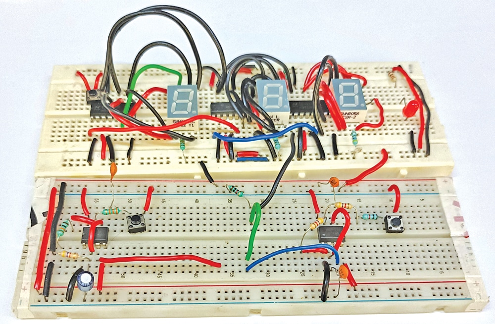 Fig. 1: Creator’s prototype
Twin Stopwatch Circuit and Working
The circuit diagram of the twin stopwatch is proven in Fig. 2. It’s constructed round two NE555 timers (IC1, IC2), three 4033 7-segment show drivers (IC3 via IC5), three widespread cathode 7-segment shows (DIS-1 via DIS-3), and a number of other different parts.
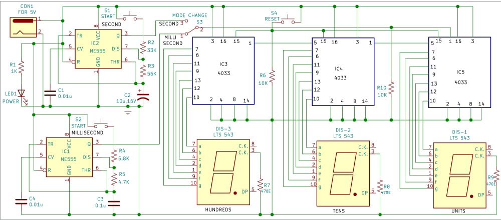 Fig. 2: Circuit diagram
The 4033 IC facilitates straightforward interfacing with 7-segment shows and is flexible for purposes like decade counting, seven-segment decimal shows, watches, and timers.
Timers IC1 and IC2 function in an astable multivibrator mode, producing millisecond and second pulses, respectively. The outputs of those timers are routed to the three 4033 ICs (IC3 via IC5) to show items, tens, and a whole lot of digits.
Elements ListSemiconductors:IC1, IC2– NE555 timerIC3-IC5– 4033 decade counterDIS-1-DIS-3– LTS543 widespread cathode 7-segement displayLED1– 5mm purple LEDResistors (all 1/4-watt, ±5% carbon):R1-1-kilo-ohmR2-33-kilo-ohmR3-56-kilo-ohmR4-5.8-kilo-ohmR5-4.7-kilo-ohmR6-10-kilo-ohmR7-R9-470-ohmCapacitors:C1-C4– 0.01μF ceramic diskC2– 10μF, 16V electrolyticC3– 0.1μF ceramic diskMiscellaneous:CON1– DC socketS1, S2, S4– Push-to-on switchS3– SPDT change– 5V DC adaptor
Switches S1 and S2 provoke and cease the stopwatch for milliseconds and seconds, Swap S3 permits mode change, and Swap S4 resets the stopwatch. A 5V DC socket powers all the circuit, with LED1 indicating energy presence.
On this stopwatch circuit, the delay in seconds is generated utilizing IC2, and the length of the delay relies on the worth of the resistor used. The calculation components for producing frequency for the astable multivibrator (constructed round IC2) is:
F=1/T=1.44/(R2+2R3) C2
Right here R2 is 33k, R3 is 56k, and C2 is 10µF.
Equally, astable multivibrator IC1 generates millisecond delays. The stopwatch operates by triggering the 7-segment decoder 4033 with pulses from the astable multivibrators.
The working of the stopwatch is simple. As an example, if you wish to measure 50 seconds, set S3 to the seconds place, press reset change S4, displaying 000. Press begin change S1 till the show exhibits 050, then launch change S1 to cease counting.
For measuring 500 milliseconds, observe an analogous course of with S3 within the millisecond place, urgent reset change S4, displaying 000. Press begin change S2 till the show exhibits 500, then launch S2 to cease counting.
PCB Design
An actual-size, single-sided PCB format for the twin stopwatch is proven in Fig. 3, with the element format in Fig. 4. After assembling the circuit on the PCB, enclose it in an appropriate field, inserting LED1 and CON1 on the entrance facet. Place the PCB to permit straightforward viewing of the three 7-segment shows for time studying. Repair switches S1 via S4 on the entrance or higher facet for handy entry.
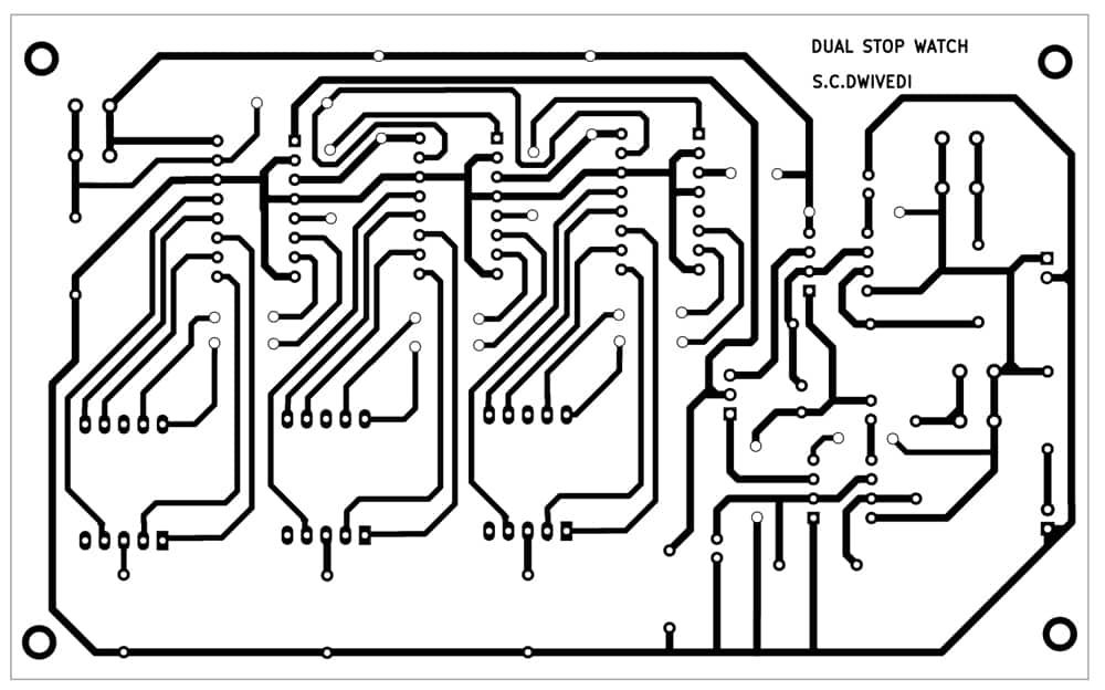 Fig. 3: Precise-size PCB format
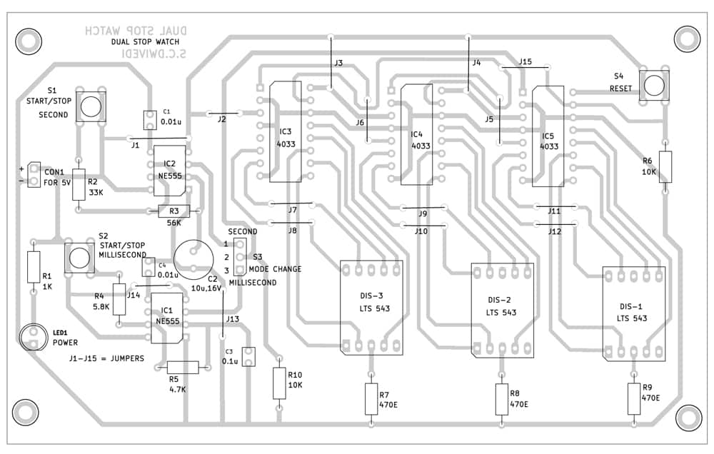 Fig. 4: Part facet of the PCB
LED1 ought to illuminate upon connecting a 5V adaptor throughout CON1, indicating the twin stopwatch is prepared to be used.
Bonus. You’ll be able to watch the video of the tutorial of this DIY challenge at: https://www.electronicsforu.com/videos-slideshows/live-diy-dual-mode-stopwatch
S.C. Dwivedi is an electronics fanatic and circuit designer at EFY
[ad_2]
Supply hyperlink

