
[ad_1]
 Remark errors or corrections discovered for this circuit, and get the prospect to win massive!
As the harmful hazards of mosquitoes are rising day-by-day, the utilization of liquid digital mosquito repellents is rising daily. Liquid Digital mosquito repellents are used broadly for night time’s sleep and are additionally generally utilized in places of work for a greater day’s work. Inhalation of mosquito repellent vapour is inflicting dangerous respiration results and allergic reactions. Most liquid digital mosquito repellents are rugged in building and function repeatedly as their switched on.
The continual operation of the liquid digital mosquito repellent repeatedly vaporises the liquid which the content material of the vapour within the room exponentially will increase with time. Right here we introduce good timing operation for the liquid digital mosquito repellent which accommodates totally different modes of operation appropriate for all residential and workplace functions.
Circuit and Working
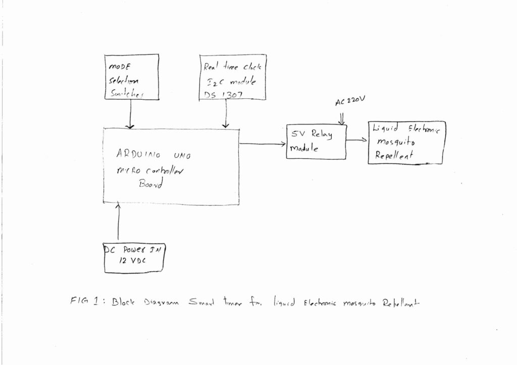
The block diagram of the good digital mosquito repellent timer is proven within the determine 1. The block diagram primarily consists of the arduino board which is the center of the system , centred round ,the actual time clock, the mode choice switches and a 5 volt relay board. The principle thought of the timer is to change ON and OFF the liquid digital mosquito repellent in line with totally different modes of operation. Right here for comfort now we have taken 7 totally different modes that are chosen by the three choice switches.
Mode 1: Night time mode:
That is the overall function mode, the place most a lot of the family throughout night time makes use of it , for undisturbed sleep. On this mode, the controller robotically switches on the mosquito repellent between 18:00hrs. And 6:00 a.m. Repeatedly with none interruption. It robotically switches OFF after 6:00 a.m. Most frequently occasions, we change OFF the repellent at totally different irregular occasions which is possible to us. This behavior causes the exhaust of the liquid and in addition pointless vapour into the room.
Mod 2: Night time toggle mode
On this mode, the timer switches on the repellent repeatedly from 18 hrs. to 00:00 Hours. Later it toggles from 00:00hrs to six:00 a.m. On hourly foundation. Within the night the doorways are opened and closed fairly often, so there may be numerous want of the vapour within the room to kill the mosquitoes.
– Commercial –
Resulting from this steady operation of the repellent the vapour within the room will increase exponentially. The excessive vapour focus within the room just isn’t required in the course of the late night time hours. After late night time hours ie: After 00:00 hrs the repellent is change ON and OFF on hourly foundation as much as 6:00 a.m. Within the morning. The toggling of repellent after late night time hours reduces the focus of the vapour and protects us from inhaling the vapour excessively
Mod 3: Night time toggle mode with buzzer
This mode is much like Mode 2 operation. The extra characteristic of this mode is that it finally ends up with a buzzer which acts as a wake-up alarm.
Mode 4: workplace Mode
This mode is used when the mosquito repellent is utilized in places of work. It switches on repeatedly in the course of the workplace hours between 10:00 a.m. To 18:00 hrs. Remainder of the time it’s switched OFF. This mode is utilized in opened workplace rooms ( doorways open ).
– Commercial –
Mod 5: Workplace toggle mode
On this mode, the repellent is switched ON and OFF on an hourly foundation in the course of the workplace between 10:00 a.m. and 18:00 hrs. This mode is usually utilized in closed air-conditioned workplace rooms.
Mode 6: Corridor mode
This mode is mostly utilized in a halls, the place the household collect throughout night occasions in residential homes. The timer switches on the repellent between 17:00 to 22:00.
Mode 7: all day toggle mode
This mode works all of the day, 24 hours with a non-continuous operation. On this mode, It switches ON and OFF the repellent on hourly foundation. This mode is mostly utilized in workplace rooms which work 24 / 7
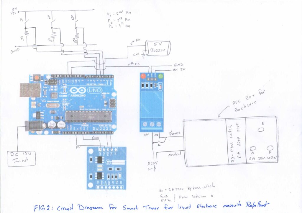
The 7 modes are managed by these switches p1 P2 P3 as proven in Determine 2. The switches are easy SPST switches related in sequence with the resistor between the 5 volt and the bottom pin of the Arduino board. The output of the switches are related to the audio board pins that are proven in desk 1. The place of the switches and the corresponding modes of operation are proven in desk 2.
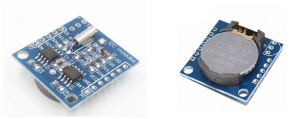
The controller wants the timer enter for comparability with the set occasions. For this operation DS 1307 I2C RTC module is used and proven in Fig 3.
This module retains the clock working. The DS1307 serial real-time clock (RTC) is a low-power Battery-Backed by lithium CR 2032 3Volt, and the information ( seconds, minutes, hours, day, date, month, and yr info) are transferred serially by means of an I2C, bidirectional bus. Aside from the facility provide, solely TWO pins SDA (information line) and SCL (clock line) are required for establishing the I2C communication. The pin connection to the I2C module and to the Arduino board are proven within the circuit diagram.
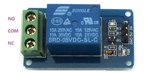 Channel 5V Relay Module
5 5-volt buzzer is related to pin 12 of the Arduino board. And, the bottom pin of the Buzer is related to Arduino floor.
Desk 1: Arduino UNO Pin Connections With ComponentsArduino UNO PinsComponents5V pin DS 1307 I2C RTC module VCC pinConnected to VCC pin Of Relay BoardTo switches P1,p2,p3Pin 2 Swap p1 out putPin 3Switch p2 out putPin 4Switch p4 out putA4SDA pin of DS 1307 I2C RTC moduleA5SCL pin of DS 1307 I2C RTC modulePin 11Input sign pin Of Relay BoardPin 12Buzzer optimistic pin GND Related GND pin Of Relay BoardConnected to DS 1307 I2C RTC module GND pinConnected to buzzer GND pinResistors R1, R2 , R3,
The Software program and Code
The Circuit operation is carried out by means of the software program program loaded into the inner reminiscence of Arduino UNO. This system/sketch is written in Arduino programming language. ATmega328P on Arduino UNO comes with a pre-programmed boot loader that permits customers to add a brand new code to it with out utilizing a peripheral {hardware} programmer.
Arduino IDE is used to compile and add this system. The sketch is the center of the system and carries out all main capabilities. This system is simple and easy to grasp. Feedback are given on the finish of every command line. Enter and output pins are initialised. The next capabilities and libraries are used.
 DS 1307 I2C RTC Module
Serial.start(): Establishes serial communication between Arduino UNO board and one other system, through a USB cable. It permits the 2 gadgets to speak utilizing a serial protocol. Right here serial communication is used solely to only learn the information from Arduino UNO onto the display screen. The displayed information permits us to know the time, and dealing mode
On this venture, the next header information are utilized in the primary code.
#embody <Wire.h>. The Wire library permits to speak by means of I2C gadgets, additionally referred to as “2 wire” or “TWI” (Two Wire Interface). The SDA (information line) and SCL (clock line) are used for speaking with DS1307 RTC Module.
#embody “RTClib.h”. Used For speaking with the DS1307 RTC module.
Within the subsequent step , initialize the relay and ISD1820 MODULE P-L PIN as output.
Serial.start(9600); used for serial communication. To show the time on the serial display screen.it’s used for simply reference function.
Two strategies of setting the time into the RTC module:
Technique 1:
rtc.modify(DateTime(F(__DATE__), F(__TIME__))); This line units the time in line with your laptop time. It’s going to set the current clock time of your system in to the DS 1307 I2C RTC module.
Technique 2:
rtc.modify(DateTime(2021, 7, 21, 10, 0, 0)); This command will set the time into the RTC module on this format ( yr, month, date, hours, min, seconds.) (ie 2021, JUL, 21, 10:00:00 am). As soon as the time is about, the backup battery within the RTC module retains the time for a really very long time.
You may view Desk 2: right here
Precautions
The Arduino UNO boards are extremely delicate. Deal with fastidiously.
Verify the DC energy provide jack enter polarity ( 2.1mm center-positive plug into the board’s energy jack).
Elements Listing
ARDUINO UNO board
DS1307 RTC Module
5V Relay module
Jumper wires
Mini breadboard
R1,R2,R3 -10k ohm
P1,p2,p3- spst switches
S1 electrical 6A change
12V DC energy provide with 2.1mm center-positive plug
Okay. Murali Krishna presently working as a junior engineer ( telecom methods ) set up and CDOT playing cards restore middle, BSNL, Rajahmundry Andhra Pradesh. He’s an electronics fanatic, circuit designer and technical article author.
[ad_2]
Supply hyperlink

